Original Link: https://www.anandtech.com/show/869
Digital Visual Interface (DVI) Explained & Improving GeForce2/3 Image Quality
by Anand Lal Shimpi on January 17, 2002 1:54 AM EST- Posted in
- GPUs
We always complain about relatively minor differences in performance between chipsets, motherboards and even CPUs yet very little attention is paid to one of the most important aspects of computing - video output quality.
Over the past few years, as 19" and 21" monitors have become more common users began noticing that the output from their video card wasn't as clear as could be. Issues such as overly blurry text and an inability to read smaller fonts were present, and because they were present when running normal applications in Windows this was incorrectly referred to as poor "2D image quality." We're not exempt from the guilt, as we have performed our own subjective "2D image quality" tests of various graphics cards in the past - but bear in mind that these image quality issues affect all output from your video card, not only 2D windows.
To understand why this occurs you must understand that the connection between your video card and most monitors is still an analog connection. What do we mean when we say "analog?" While it is true that the underlying basis behind all digital circuitry is a collection of analog components, a digital system only understands two discreet values. When you transmit a 1 digitally you'll get a 1 as your output, regardless of voltage fluctuations or any other phenomenon that occur during the transmission so long as the digital components can function properly. Whereas with an analog system, the possibility that a 1 could end up looking like a 0.935 or a 1.062 exists and thus introducing a level of uncertainty where the picture your video processor outputs won't necessarily be the same was what you see on your monitor.
For example, imagine an analog connection between your keyboard and your computer. If the analog to digital converter on your computer's side misinterpreted the signal coming from your keyboard, then typing an 'h' could very well come out as a 'j' on your screen. Similarly, the blurriness that may be present at higher resolutions isn't what's being outputted by your graphics chip. The data to be displayed on your screen leaves the video card's frame buffer (memory) as digital data but before it can leave your video card it must go through a RAMDAC. The RAMDAC (Random Access Memory Digital to Analog Converter) converts the digital data into an analog signal and it used to be the culprit for poor image quality not too long ago. Today's RAMDACs are much higher bandwidth and are of considerably higher quality, thus making quality loss because of the RAMDAC less of an issue than it once was.
After being processed through the RAMDAC the analog signal leaves the video card, through your VGA cable (another source for signal quality loss) and enters your monitor. The signal loss is compounded even further if you have a digital flat panel instead of a conventional analog CRT as the lower quality analog signal is then converted back to a digital form. It is this last stage that makes very little sense because just a few steps ago we were dealing with a completely digital signal leaving your video card's frame buffer; this is where DVI comes in.
Today we'll talk about the Digital Visual Interface (DVI) and how it is shaping up to eliminate these transmission problems when it comes to PC monitors. We'll also be talking about DVI implementations in currently available video cards, as well as how to improve your present-day analog video output if it's not so hot.
What is DVI?
Other than "that white connector on my video card that I've never used" DVI is a very important standard. Behind the standard is a group of companies that together form the Digital Display Working Group (DDWG), among the key players are Intel and Silicon Image, but we'll address why they are key players later on.
The DDWG came to the realization of the same problem that we just outlined in our introduction where it makes no sense to convert digital data to analog just to eventually convert it back to a digital form. The purpose of the DVI spec was created mainly with the thought that displays would be moving towards the digital domain in the future. The fact that we're still not all running digital flat panels is a very good reason for why we all aren't as familiar with DVI as we should be.
The specification is relatively simple to understand; data is transmitted using what is known as the transition minimized differential signaling (TMDS) protocol. This serial encoding protocol is what is used to transmit data over a DVI connection and it was created by Silicon Image; it shouldn't be a surprise that when it comes to TMDS transmitters, Silicon Image ICs are used much more frequently than any others. The DVI specification calls for at least one TMDS "link" which consists of three data channels (RGB) and one clock control channel.
Two TMDS Links - Taken from The DVI Specification 1.0
According to the DVI specification, a TMDS link may operate at up to 165MHz. A single 10-bit TMDS link offers 1.65Gbps of bandwidth which is enough for a 1920 x 1080 resolution refreshed at 60Hz on a digital flat panel. The maximum resolution depends on the amount of bandwidth required to display the resolution as well as the efficiency of the device it's being sent to. This is beyond the scope of this article but it's worth noting that there are differences between the maximum attainable resolutions on various display technologies.
In order to keep the specification as flexible as possible, a second TMDS link may be used. This link must operate at the same frequency as the primary link, meaning that in order to obtain 2Gbps of bandwidth each link must operate at 100MHz (100MHz x 2 x 10-bits).
It is mainly because of its high-bandwidth abilities that DVI was the standard that emerged victorious among all of the competing solutions.
DVI-I vs. DVI-D
Another benefit, albeit very infrequently utilized, of the DVI specification is the ability to support both analog and digital connections on a single interface. The DVI connector can be seen below:
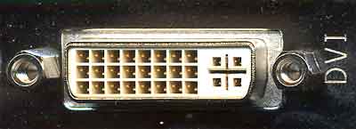
On the left you'll notice 3 rows of 8 pins each; these 24 pins are the only pins required to transmit the three digital channels and one clock signal. The crosshair arrangement on the right is actually a total of 5 pins that can transmit an analog video signal.
This is where the specification divides itself in two; the DVI-D connector features only the 24-pins necessary for purely digital operation while a DVI-I connector features both the 24 digital pins and the 5 analog pins. Officially there is no such thing as a DVI-A analog connector with only the 5 analog pins although some literature may indicate otherwise. By far, the vast majority of graphics cards with DVI support feature DVI-I connectors.
The idea behind the universal nature of this connector is that it could eventually replace the 15-pin VGA connector we're all used to as it can support both analog and digital monitors.
What to do about scaling?
A major problem when dealing with digital flat panels (the primary market for the DVI spec) is that they have a fixed "native" resolution that they can properly display at. Since there are a fixed number of pixels on the screen itself, attempting to display a higher than native resolution on the screen is impossible.
It is quite often however that a lower resolution will be displayed on the screen; case in point would be the Apple 22" Cinema Display monitor with a native resolution of 1600 x 1024. Playing a game at that resolution would be silly not to mention that most games don't even support such odd ratio resolutions, and thus you'd have to play at 1024 x 768 or 1280 x 1024. The problem with this is that the image must now be scaled to properly be displayed on the screen.
It used to be that scaling was not even considered an important matter and was left ignored but as digital flat panels increased in popularity it became something that manufacturers worried about. The DVI specification places the duty of properly scaling and filtering non-native resolutions where it should lie, on the monitor manufacturer's shoulders. So any monitor that is fully DVI compliant should handle all scaling/filtering itself and obtaining a relatively nice scaling algorithm is not too difficult meaning there shouldn't be much difference between monitors in this respect (although we're sure there will inevitably be some).
DVI Support in Current Graphics Cards
With the release of the GeForce2 GTS, NVIDIA had integrated a TMDS transmitter into their GPU that would remain there even to this day in the current Titanium line of cards. The problem with this integrated TMDS transmitter was that it ran at too low of a clock speed to support higher resolutions. It seems as if the integrated TMDS transmitter did not and currently does not operate at the full 165MHz capability of the link, leaving the DVI implementation in NVIDIA GPUs relatively useless on its own for higher resolution displays.
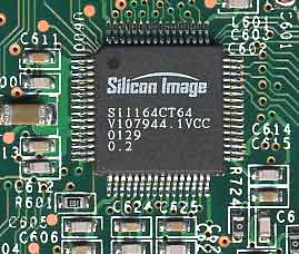
If your NVIDIA card has a DVI connector, you'll most likely find one of these
on the card as well
In order to address these shortcomings, NVIDIA boards are outfitted with a second external TMDS transmitter generally one manufactured by Silicon Image. Depending on the design of the board this transmitter could either work as a second link in conjunction with the GPU's integrated TMDS link or it could bypass the integrated TMDS just as easily. It is unclear exactly why NVIDIA's integrated TMDS isn't up to the task but if they did eventually fix the issue it could save board manufacturers a bit in manufacturing cost to not have to include an external TMDS on every graphics board. Because of this external TMDS, resolutions up to 1920 x 1440 can be used via the DVI-I connector.
You may run into some NVIDIA cards with a DVI connector that simply won't work with a DVI display plugged in. We conducted an informal test of a few of the DVI equipped cards we had in the lab and although all of the newer Titanium cards worked just fine, the Gainward GeForce3 would not work nor would NVIDIA's Reference GeForce2 MX. If you have one of the newer Titanium cards you should have no problem running at any of the higher resolutions, although most documentation still states a maximum of 1280 x 1024. We confirmed this on an Apple Cinema Display at 1600 x 1024 on all of the Titanium cards with DVI connectors in our upcoming Titanium Roundup.
The story with ATI is completely different as all DVI equipped ATI cards have their digital outputs driven from the integrated TMDS on all ATI GPUs. ATI found an interesting way of taking advantage of the DVI-I connector by shipping some cards with a DVI-I output and a DVI-I to analog VGA dongle. The dongle essentially takes the 5 analog pins from the DVI-I connector and connects them to a VGA pinout.
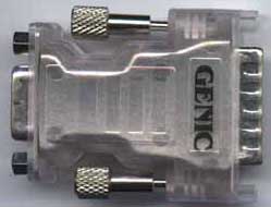
The ATI All-in-Wonder Radeon was the first ATI card to ship with this DVI to VGA dongle
Matrox happens to be the only desktop graphics manufacturer with a dual DVI solution on the market. The Matrox G550 is available with a dual DVI cable however Matrox states that the maximum resolution per DVI monitor is still only 1280 x 1024. Since we could not confirm or refute this statement through our own tests we can only suggest that you approach with caution if you plan on using a higher resolution.
Final Words: What to do until DVI - Improving Image Quality on NVIDIA cards
Instead of closing on a "it'll be great once everything uses DVI" quote, we'll leave you on a more practical note. There are many downsides to being the most popular graphics card manufacturer on the planet, and for NVIDIA one of those happens to be that they cannot strictly control and monitor the production of all boards that carry their name. By allowing third party manufacturers (such as ASUS, Chaintech, Gainward, Visiontek, etc…) to produce boards for them, NVIDIA is leaving the role of quality control in the hands of their manufacturers. For the most part, because of the reference designs that NVIDIA provides there are relatively few problems with these third party boards. One of the relatively few problems that do exist is the issue of image quality.
In order to maintain FCC compliance, a low-pass filter is placed just before the analog video output on all cards. A low-pass filter is nothing more than a filter that allows frequencies lower than a certain point to pass through, effectively filtering out all higher frequencies that are not necessary to maintaining the quality of the output signal.
The problem with NVIDIA cards arises when a third party manufacturer's low-pass filter filters out some of the important frequencies as well as those that aren't needed. It is unlikely that the capacitors and inductors that make up the low-pass filter are deliberately chosen to be of poor quality, rather the rating of the components is not up to par with what NVIDIA's specifications call for. Another possibility is that when these third party manufacturers purchase the components for these filters some end up being of higher quality than others. This would explain the seemingly sporadic nature of what cards in particular have these image quality issues. Regardless of what the reason behind the low-pass filter causing these issues, there is a quick and dirty fix for the problem - remove the low-pass filter. This has been documented in the past here, but hope to present this information to a broader audience with this article, as well as to provide some of our own insight on how to perform this mod in the simplest possible fashion.
Note that by removing the low-pass filter you will be voiding your warranty on your card and we cannot be held responsible for any damage done to your card. With that out of the way, the process is actually very simple. On all NVIDIA reference designs since the original GeForce, the low-pass filter is readily identifiable by 3 sets of 3 capacitors connected in parallel with 2 sets of 3 inductors in series near the VGA output connector. The 3 sets are for the 3 components of the RGB signal being sent to your monitor - red, green, and blue. Most board designs also offer a set of protection diodes as well although not all of these components will be found on all boards.
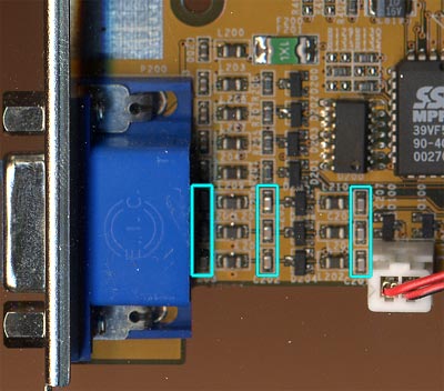
On this GeForce2 Pro, the cyan boxes enclose the 3 sets of 3 capacitors. These capacitors must be clipped off. From left to right you can see the first column of capacitors, then a column of inductors, the second column of capacitors, then a column of protection diodes, another column of inductors and the final column of capacitors.
On GeForce3 boards with a DVI-I connector, the low-pass filter is located near the DVI-I connector. If there is no DVI-I connector present then you'll find the filter components either near the VGA output or where the DVI output would be located if it were included.
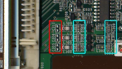
This Visiontek GeForce3 Ti 500 already has one column of capacitors removed (red box), so it's no surprise that it also has very good image quality. These capacitors are located near the DVI connector on the board. When you've clipped the capacitors all that should remain is what you see in the red box above.
The fix is accomplished by merely clipping off the 9 capacitors using a pair of needle nose pliers; this won't harm the board if done properly. The end result depends on how bad the image quality of your card was prior to the mod. We have seen results ranging from virtually no change at all to a dramatic improvement, even on a card that had pretty crisp output to begin with.
To completely remove the low pass filter, you'd want to short the inductors to bypass those as well. Our experience has shown that this considerably more complicated procedure has yielded diminishing returns once the capacitors have been removed.
Again by removing this filter you are allowing higher frequencies to pass through that normally wouldn't which could cause interference with other devices, although it's highly unlikely.
Update: We must warn you against removing what may look to be capacitors from your card. Certain boards do not implement a third row of capacitors as seen in the pictures above, rather they feature a row of resistors. The below picture is from a Visiontek GeForce3 Ti 200:

The three red boxes enclose three resistors which should not be clipped. The yellow box encloses a capacitor which can be clipped. By removing the remaining 6 capacitors and leaving the three resistors untouched you should be able to obtain similar results with this mod.
Why is this mod not necessary on ATI and Matrox cards? Until recently both ATI and Matrox manufactured all boards based on their chips by themselves and thus had very strict control over all component sourcing. We have yet to see whether ATI's decision to allow third party manufacturers to produce ATI graphics cards will result in the same issues end users face with image quality on NVIDIA cards.
Eventually worrying about image quality loss as a result of poor RAMDACs or subpar low-pass filters will be a thing of the past and the DVI standard will help to ensure that.


